
I spent too much time in too small, too busy meeting rooms, discussing about who knows what and too many times I felt the oxygen was letting me down. Was there too little oxygen? Or too much carbon dioxide? Or still something else? Time to find out and build my own CO₂-meter.
On Sparkfun I found a CCS811 air quality sensor on a breakout board. It can not only measure the carbon dioxide (CO2) level in the air but also the level of so-called total volatile organic compounds (TVOC). It has an I2C interface, so you must use it in conjunction with a microcontroller. But the CCS811 is a wonder on its own, because it contains a microcontroller in itself to pre-process the data. The catch is, that the CCS811 can only tell the CO₂ and TVOC by any accuracy when you tell it the temperature and humidity.
So we need a second sensor in order to find out temperature and humidity and Sparkfun has a solution for that too: the BME280, which not only measures temperature and humidity, but also air pressure. This one is also available on a breakout board and also uses a I2C interface. As a matter of fact, the wires of the two sensors can be connected in parallel on the I2C interface. The can be distinguished because they use a different address on the bus!
What else to throw in? An ATMEGA328 microcontroller, a 36 mm, 128×128 TFT display based on the ST7735 and a project box! The display was lying around in one of my drawers and Adafruit supplies drivers for it.
In the next steppenplan I will describe how I started this project with an Arduino Uno, then got rid of all the unnecessary stuff on an Arduino and moved to just the ATMEGA on a pcb.
Step 1: Use an Arduino, connect the CCS811, the BME280 and the TFT display
The tricky bit here is that the Arduino runs on 5 V, whereas the sensors just need 3.3V. This means not only that the supply voltage is different, but we must also take care of the signal wires. So we need and 78L33 for the 3.3V supply voltage and two level shifters based on 2N7000 for the I2C wires SCL and SDA. And this is what the schematic looks like, when it’s hand-drawn: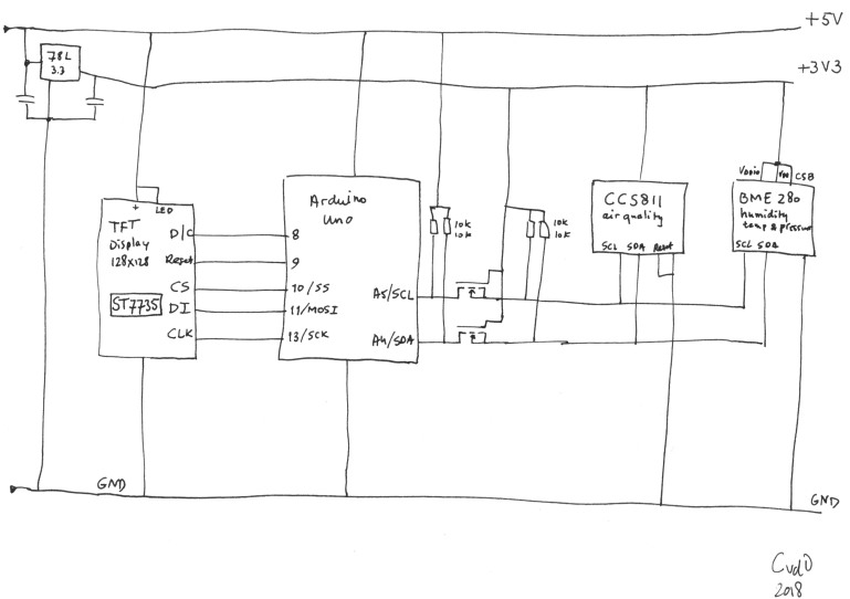
My CCS811 breakout board has a WAKE connection (shown as Reset in the drawing) which should be grounded. The BME280 on the other hand has two pins that must be connected to Vdd (+3.3V).
An Arduino sketch, based on the sketches or Sparkfun & Adafruit combined, and we have the first working prototype on a breadboard (forgot to take a picture of that, sorry!)
Step 2: Get rid of the Arduino, use a bare ATMEGA328
One of the nice things of the Arduino Uno is that its ATMEGA328 is in a socket. So we can just take out after programming and use it on a breadboard pcb. The only thing we need to add is a 16MHz crystal and a few capacitors:

Step 3: Everyone on reduced diet!
We can run the ATMEGA328 on 3.3V, it doesn’t require 5V! And as it turns out, also the TFT display runs perfectly well on 3.3V. Even more so: even on 3V all the components are within specs, so we can run the whole thing on two 1.5V batteries.

Step 4: The fall of the crystal (and a few resistors)
There’s two more things we can improve. The resistors on SCL and SDA can be removed if we enable the pull up resistors in software. This can be done in the Arduino sketch. The other thing is the crystal. Because this application is not timing critical, we can run the ATMEGA from its internal RC oscillator at 8MHz. It makes is slower, true, but that doesn’t really matter here. The way to do this, is program a “fuse”. Connect a programmer to the MISO, MOSI, SCK and Reset pins of the ATMEGA. I use a cheap USBASP programmer (less than €2 on Ali) and give the following command:
avrdude -p m328p -c usbasp -B 8 -U lfuse:w:"0xE2":m
Now the ATMEGA is programmed to use its internal oscillator at 8MHz and we can remove the crystal and its caps:
Step 5: Soldering!
I though about designing a pcb and having it produced, but it turned out a be such a simple diagram, that I found I might just as well build it on a prototype pcb. The photo below shows what it looks like (already in the enclosure that I made in step 7). Note the two beak-out boards for the two sensors (the purple and black things on the left), they are stacked together on top of each other. The purple breakout board contains the CCS811 and is a little bit larger than the breakout board for the BME280. Most of the pins line up perfectly, so it’s very easy to interconnect them in this way. And it is important that the two sensors are as close as possible to each other, because the temperature and humidity readings of one are used to compensate the measurement of the other.

By the way, these aren’t the original breakout boards from Sparkfun, they are cheap clones with slightly different pinouts. But they still contain the original sensor chips, at least that’s what I assume…
I wanted to make a tidy drawing for this blog, so as an experiment I installed Microsoft’s DrawingBoard Pro. It is supposed to be a circuit drawing/editing program especially for prototype boards and can be downloaded from Microsoft’s store. I have no idea why they put the word PRO behind this ***ware, because what does PRO mean? “PROduced in a few hours”? “PRObably the dullest tool in the shed”? Anyway, this was the first and last time I used DrawingBoard and this is what I drew:

Note that we’re looking at the bottom of the components, so pin 1 of the ATMEGA is top left. Nevertheless, I was confused myself and put the sensors on the opposite side of what I designed and now the pcb lies at an angle. Ugly, my fault.
Step 6: Design an enclosure
I decided to re-use an old enclosure, because it already had a battery compartment for 2 AA cells, which would come in handy. It’s the grey thing on the photos. But then the top lid contained so many holes in the wrong places, that I decided to 3d-print an enclosure of my own design. That’s the bright blue thing. I used Google sketchup, Cura and an Anet A6 3D-printer. Great exercise in 3D-design.

The tricky bits were the pillars for screw holes, the vent holes, the notches for the power switch and the general sizing of everything so that it would fit exactly on the existing underside. Well, I had to redo it several times before it fitted nicely…


And there is the final product: the CO2 meter-in-a-box. It shows temperature, air pressure, relative humidity in %, CO2 level (in parts per million) and the TVOC level. A CO2-level of 400 is normal for outside air (it used to be lower, a hundred years ago and before the industrial revolution, but that’s a different story) and is the minimum the CCS811 can measure. When I held the meter over an open can of soda, the value quickly rises to 4000 or so. The maximum is 8192ppm.
Then it shows the Total Volatile Organic Compounds (in parts per 1 000 000 000). Alcohol is a VOC, so when I held the meter near an open can of beer, it rose quickly towards its maximum value of 1187ppb.
I hoped you liked this process, starting with an Arduino Uno and a few break-outboards and ending with a showable prototype. There is still some room for improvement. I didn’t do the last step: get rid of the breakout boards and design a pcb. Also the way the display sits in the enclosure could be improved.
Charles

Hi,
Good work. One question: your readings of TVOC seems a bit low to me…. Are you sure of this ?
One suggestion also: I would put a very tiny fan in the case, activate it for 5 seconds, wait 10 seconds and then take the measures.
By doing so, you avoid the air remaining static in the case, and this should probably enhance the responsiveness of the sensors to the ambiant conditions
LikeGeliked door 1 persoon
Hi Pinhead, thanks for your response. Am I sure of the readings? Well, not really, this is my only air quality meter so I have no reference. The pictures where the TVOC is 0 were taken right after I turned the module on, so probably there was no reading yet. There is one photo where the TVOC is 1 ppb, that must be a reading after a minute or so. The datasheet of the CCS811 states “run CCS811 for 20 minutes, before accurate readings are generated.”. Finally, I tested the meter by breathing into it, or over a can of beer, and both CO2 and TVOC readings skyrocketed, so it does *something*!
About the fan: On the hackaday forum there were some comments more or less saying that the air should be standing still during measurement. I didn’t find any base for that in the datasheet, so I’m not sure about this. I just put a lot of holes in the case to let the outside air in… What I’ve done up to now, is move the meter around a bit and then hold still to read the values.
The meter appears to generate its own heat while being on. Although the CO2 and TVOC readings are compensated for that, the temperature reading is not reliable (maybe only the first measurement).
LikeLike
Hi,
nice to see projects on indoor air quality! But I’m awfully sorry that guys like CCS and the likes keep fooling people with their “CO2”-values or “equivalents”. Those sensors cannot measure CO2, they are metal oxide sensors, reacting to, well, reactive gases. That can be oxidized or reduced. CO2 is very stable, so metal oxide sensors just don’t see it. So, sadly, your CO2 meter is not able to measure CO2. Why do sensor manufactures state such nonsense? This comes from an old tradition in indoor air hygiene, founded by Pettenkofer in the 19th century, when he established a 1500ppm limit for CO2 from many experiments. But the guy just could not measure anything but CO2 at the time.
There are special (very expensive, ~100€) catalytic solid state sensors for CO2, but they are still crap.
Best are optical sensors (NDIR cells). They are not quite cheap, but at around 40€ you get a rock-solid signal you can rely on. Look out for E+E’s EE893 or Sensirion’s SCD30 sensor. How about including on of these into your device and compare readings between NDIR and CCS sensor?
By the way: You could use a BME680 instead of the 280, the 680 has a built-in VOC sensor so you get rid of the CCS completely.
Keep on the good work!
LikeLike
Hi Wolfhard, thanks for all the information. That would be a really interesting idea. The EE893’s price is a bit steep (starts from €75) but the SCD30 (€50)…have to think about it.
LikeLike